Multistrada 1200 – replacing the OE horn with a Stebel Nautilus
See also: Multistrada 1200 Stebel Magnum Horn Installation
See also: How to split and fit a Stebel Nautilus (ukGSer forum)
Not a Multistrada install but additional info and photos that may help;-)
See also: Super Simple Stebel Nautilus Horn Install (external link)
Alternative install location for complete horn system (i.e. compressor and resonator/horn not split)

You may be interested to know that Stebel is an Italian company that was founded in 1955 by Leonardo Beltrame. Stebel engineers and produces exclusively signal horns.
Italian replacement horn for your Ducati Multistrada 1200 Italian steed 😀
UPDATE: There is now a ‘2nd generation’ Nautilus horn which has a weather shield fitted which may make it harder to split.
Tip: If the compressor is mounted out in the weather it needs to be mounted vertically to prevent water entering the air inlet.
Tip: Use a reinforced hose between the compressor and trumpet as it is less likely to get kinked and cause blown fuses and/or overheated/damaged compressor.
Fitting a Split Stebel Nautilus compact horn to a Multistrada 1200
A guide to splitting and installing a Stebel Nautilus air horn system.
By Ducati.MS member ‘TimOz’ 10Sep2010 (see forum discussion here)
Larger photos and a few extra can be found here.
This is my first technical write up for this site, so please be nice 🙂
I spent a few years riding around Singapore and Malaysia where the road rules are based on the price of your car and no one seems to have spacial sense. A Mercedes beats a BWM which beats a Toyota and Bikes are dead last. I learned the value of fruity cans and a loud horn!
The Stebel Nautilus Compact horn is excellent, loud and small but it is sometimes hard to find enough space to fit it. It costs about $50. While it will fit straight on many motorcycles / bikes, it can be obtrusive and ugly. You may not know that it is possible to easily split the compressor component from the resonator horns and fit them separately with an air tube between. This allows many more options as to where to place them on the bike. This is how I did it on my 2010 Multistrada 1200 / MTS1200S.
How to do it:
The Stebel nautilus Compact components

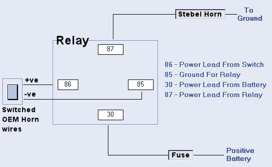
Basic wiring diagram from Andy’s Stebel magnum horn install article
The compressor is about 13cm long and about 5cm at the widest diameter.

Split the compressor from the resonators- it is held on by 3 things:
A tab near the air outlet from the compressor. You can just break off the tab cage as you won’t be needing it. There is a small amount of weak glue holding the compressor onto the plastic. Just slide a flat screwdriver under the plastic to break the glue.
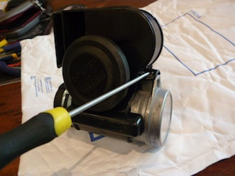
The black plastic component has a built in air intake tube that has a ridge that pits into the compressor inlet. Just lever the plastic off the compressor to lever this ridge out of the compressor air intake hole and the plastic component should slide off the compressor. Note the compressor air outlet has a small o-ring seal.

I tried to make each unit as compact as possible so I used a Dremel tool to slice the plastic component into the resonator unit and also cut the air intake section out. I left enough plastic to drill and mount a bracket. I also cut off the allow mounting point off the compressor body as I don’t need that either. I think it best to try to keep the air intake section as it is small and should help to stop water getting directly into the compressor. I glued this back onto the compressor using contact cement and rubber banded it on and left it overnight.


I found the compressor fits well in the Right side panel of the MTS but I thought it better to pad it out with neoprene. I had a drink cooler handy (Australians call this a stubbie holder) that I sliced up and cut to sive and glued on with contact cement and left overnight to dry. I then sprayed it black and it looks better in reality than the pictures. In the photos I have zip tied it onto the frame rail but I will make up a better bracket.


A brass air line fitting (I think is ¼ inch thread) can be screwed directly into the air intake hole in the resonator. It fits perfectly and you don’t even need to tap it out. I used a thin smear of silicone to make sure it seals. NOTE, don’t screw it all the way in or it can block the air flow into the resonator. Screw it in about ¾ of the available thread. Other plastic options are available but this is what I had lying around. I used 8mm silicone surgical tubing and covered it with a black wiring cover I had lying around to make it less conspicuous where it is visible. I added heat shrunk the ends. As the compressor had a conical air outlet with no barbs I glued this tube on and added a small zip tie. I routed this tubing along the frame rail and under the Right side tank cover to the Right front shroud. It is easiest to remove the Right side cover, shroud and loosen the Right side of the beak or remove it for access.

I made up a simple bracket for the resonator out of stainless from a boating shop. This is called a chain plate but you can use anything. This was bolted to the horn resonator with 2 stainless bolts, washers with nyloc nuts. I put poly plastic washers in between the bracket and the horn to add a little flexibility. The stainless bracket is twisted slightly to align the horn with the bike, allow it to fit neatly under the carbon shroud and also point the sound outlets out and down to maximize sound output and minimize water ingress.

I removed the standard horn. Note that this horn uses its mount for the vibration adjustment, so you have to loosen the nut and then wind the centre bolt like section out to remove it. I simply bolted the new horn section to the standard bracket. As the hole in the bracket is large I put a grommet in the hole and sandwiched this with large stainless washers. This again adds a little flexibility and I think this is a good thing for a horn.


Now for the power. I have a Touratech TPS15 CAN Bus Output Helper fitted (I highly recommend this) so this bit is easy. I ran a double wire from the standard horn spade connectors back to the relay that is fitted beside the TPS15. This is wired to the solenoid electromagnet. A earth wire is run to the –ve compressor terminal. A wire from the +ve compressor terminal to the solenoid switch and a wire from the other side of the solenoid switch to the +ve terminal on the TPS15. I did not fit another fuse as the TPS15 is fused.
If you have no idea about wiring, read this bit. The idea is that the CAN Bus can be very particular about electrical loads and the air compressor takes more amps than the electro standard horn. Wiring a high load device directly to the standard horn wiring is likely to trip an error in the CAN Bus system and will also overload the wiring and melt it, risking a fire. Therefore a solenoid is used that is an electrical switch. It is an electromagnet that that can be operated with a small amount of power. When the magnet is activated it lifts an electrical bridge that can carry a high electrical load. This is the click you hear when the solenoid is activated. With this set up, pressing the horn button only activates the solenoid and the CAN Bus is happy to do this. This in turn sends power directly from the TPS15 to the compressor motor and you have a loud horn. The TPS15 is wired to only supply power when the bike is on (ie the dashboard is on). The motor does not need to be running but the horn will not operate if the bike is off and I think this best.


Shrouds fitted back on. The compressor is totally hidden under the side cover and the resonator is just visible under the right front shroud. Job done.


I have had to use it about 4 times so far and EVERY time the errant car (and in 1 case a semi truck) driver became rapidly aware of my existence.
I hope you have found this useful.
Comments:
Wiring up the standard horn activation wires to a relay and wiring that to the battery is just fine.
The TPS15 is useful for 2 reasons.
1. If you add a few accessories, you end up with quite a few wires to the battery and either you can wire a couple things to a ring terminal or you end up with a stack of them and the chance of a dodgy connection.
2. The TPS has an inbuilt relay that is activated by the bikes ignition (mine is activated by the GPS +ve feed). This means that all accessories are forced off when the bike is switched off. Better for battery conservation and no idiot can activate any electrics while the bike is parked up. This is not an issue on the MTS1200 as I think the standard horn button will not be active with bike switched off.
I agree with Martinm3j that you should use heavy guage wire. The horn draws 18Amps (that is a lot) so you need a 20 or 25 amp fuse and wire that can handle this current draw or you will have blown fuses at best or melting wire and a fire at worst. I can’t tell you the wire size as Australian automotive wire is strange sizes and we would use >6mm but 10mm is better.
[martinm3j]
Yet another (third?) way to mount the horn. Figured I’d take the strategy of putting it where the evap cannister was, rather than trying to hide it. Being black/aluminum, it pretty well blends right in.
I did have to do some welding/grinding/hammering/cursing to create a very custom bracket. For you other metal bending guys, feel free to plagiarize and do something even prettier.
One more minor tweak versus other installs, I’ve made a point on all my vehicles to leave the stock horn connected. The relay for the Nautilus has a small delay, which is cool… I can do a very quick “hello” beep, and it mostly just sounds the stock horn. Or I can lay on the button, and the Nautilus kicks in a very short bit later. As long as you run good power to it (all wires except the switching wire from the stock horn were 12-ga), dual horns seem to work just fine.


